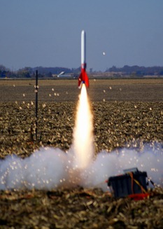
Sounds strange, but I like laminating things. Kevlar, Carbon Fiber, Fiberglass…. doesn’t really matter. Once you understand the process, it opens up a lot of options in both Rocketry, and the real world. In Rocketry, Laminating can provide key missing strength, stiffness, or just plain ruggedness to an otherwise undistinguished model. Combine lamination with foam, and a whole world of custom parts, or odd rockets can be created. In the photo on the right, you see what looks to be the launch of a boring Estes “Super Big Bertha” kit. In fact, the entire rocket was laminated with Kevlar, Carbon Fiber, and fiberglass. The end result – A kit that Este’s recommends launching with a D12-5 engine (max thrust of 29 N, total impulse of 16.8 N-s), that I launched with an Aerotech J570 (max thrust of 1142.5N, total impulse of 973.1N) – an engine about forty times more powerful. During this particular flight, I had packed the chute a bit too tight to fit in my electromagnetic ejection system. Ejection worked, but the parachute never inflated. The rocket fell from 5000 ft, and didn’t have a scratch on it when I found it about 1/2mile away. You can check out the video from the flight below (you can see the camera duct-taped to the side)
 ile I didn’t show the original fiberglassing of the magnaframe airframe, there wasn’t a lot of complexity involved. Just as I was leaving HPR rocketry the first time (thanks to the BATF), I had found a company called Fibersock that sold a knitted fiberglass “sock” that let you fiberglass a tube without any seams or complexity. Upon my return to HPR (thanks to Tripoli & NAR beating the ATF in court), Fibersock is gone, but the product is still around. Giant Leap sells a version they call “easyglas” which is exactly the same thing. Basically you pull the sock over the airframe, tie it up on either side, and slather on epoxy laminate. The only modification I’ve made to this process is to use a Teflon coated release film to ensure a very smooth surface, and no air bubbles. This is unlike any peel-ply, or release film I’ve ever used. Very easy to remove, very smooth, super easy to cut and position. Frankly, it’s so well made, when doing tip-to-tip lamination on a small rocket, I’ll often use the same piece of cut release film over and over. Only place I’ve found it i s here.
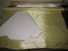
 My plan was to to do tip-to-tip lamination of the fins with one layer of Kevlar for strength, and one layer of
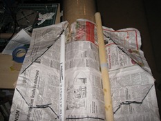 fiberglass for finishing. I’ve found Kevlar almost impossible to sand to a smooth finish once it is cured. a thin layer of fiberglass over the top of the Kevlar provides a great base to sand and smooth. I first laid some scrap newspaper over the fins to create the base outline of the fin area. I then cut out the newspaper, and used it as a base to build a cutting template out of foam board. The newspaper gave me the base dimensions, but I needed to add about 2 inches of cloth in each direction to ensure complete coverage, and allow for the Kevlar and fiberglass to wrap around the thick fin edge.
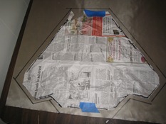 A typical rocket fin made out of g10 fiberglass would be about .093, to .125 inches thick. My fins and wings were about five times thicker, requiring some creative solutions down the road. My main goal in creating the laminating fin can is to ensure the fin’s don’t rip off during flight, and increase their strength in case the rocket lands funny. I plan on putting a LOT of time into the finish (I have an airbrush, and like to play….), and would be crushed if a great flight ended with a broken fin.
My normal method for tip-to-tip lamination is to use a fairly standard vacuum bag sealing process. Because of the size of the rocket, I could not create a bag that would encapsulate the entire lower sustainer with fins and keep a good seal. This may be possible, but I spent a LONG, LONG time on it. The primary advantage of vacuum sealing is it creates a lot of pressure on the lamination, squeezing the excess epoxy out through the r
 elease film (reducing weight), and creating a good mechanical connection between the epoxy, fabric, and fins. In my case, I was less concerned about weight, but wanted to make sure I would have a good mechanical bond, including the thick edge of the fins. There are lots of great tutorials on the web on how to do tip-to-tip lamination without vacuum sealing, but all of the ones I have seen assume you have a fairly thin fin. The best I’ve seen is here. In my case, needed ballast on the lamination to keep it tightly bonded to the fin, but I needed pressure on the edge of the fin as well. Using a fin jig as John did in the link will almost guarantee there won’t be enough pressure on the edge of the fin. I needed some kind of Ballast that would mold around the fin keeping pressure over the entire surface area during curing. I settled on using a liquid as the weight, in a waterproof bag that could hang over the fin.
I should probably mention I spent a LOT of time sanding down the fillets. I also installed the boat tail, as I decided I wanted some lamination over the edge to ensure a smooth transition between the airframe and boat tail for
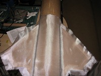
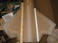
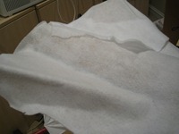
finishing. That added even more sanding. Once complete, I ‘painted’ on a layer of epoxy (US Composites), put down the Kevlar, Wet the Kevlar, then added the fiberglass. Wet the fiberglass, then added the Teflon release film. Wet the release film, then added a Polyester breather cloth on top to suck up the excess epoxy, and provide a surface for me to put down my ballast. I filled three zip-lock bags about 3/4 with water as my ballast. One bag
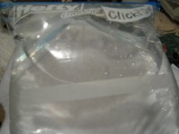
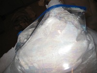
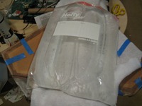
per fin, and one for the airframe & fillets. I know it’s kind of hard to see, but the bags on the fins hang over the side, providing positive pressure on the lamination during the cure. I left everything for 24 hours. Removed the water bags, then the Teflon release film.
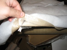
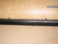
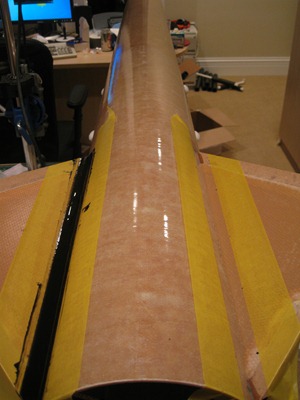
As you can see, it came out really, really well. I was a little worried with the lack of significant weight on the wings, I would get a lot of air bubbles in the lamination over the fillets. big curves like this are notoriously difficult to make sure the Kevlar and fiberglass stay pressed against the fillet, especially when the water bags were pulling on the edges of the weave to secure them around the fins. . There wasn’t one bubble tip-to-tip. Happy with the process, I then repeated it twice more for each side.
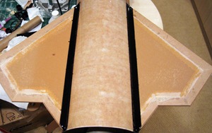
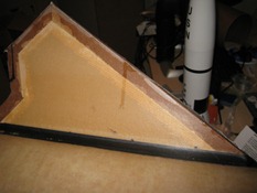 I only had two issues with the process, neither was too critical. First, on the edges of each Fin, I had doubled the lamination. The second layer of lamination didn’t have the pressure of the first, which you can see looks like an air bubble along the leading edge of the fin. This isn’t a big deal, As I will be sanding down the second layer, which is mostly fiberglass. The second issue you can also see in the picture on the left is a few epoxy runs. This is a run of epoxy over a side of lamination that has already dried. Again, not too big of a deal, just requires sanding. As you can see from the picture above, I had to laminate over the pre-cut slots for the wings to get a true tip-to-tip fin can. The pre-cuts were already too small, so the next phase will be to sand the fin can, re-cut the wing slots, and install the wings. Should start to look like a real rocket soon.
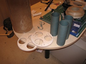
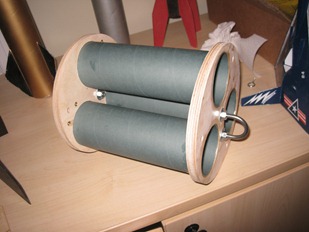
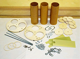 Three 2.5” x 8 phenolic tubes
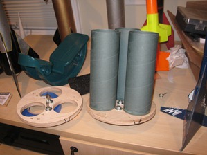 othing is ever as it seems
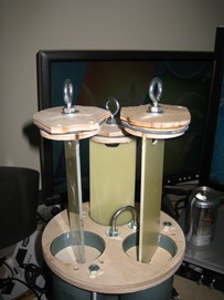
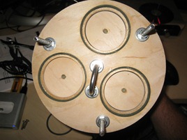
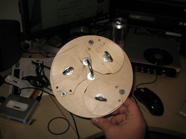
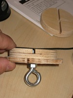 ade sure they were true, and moved to putting together the top of each pod. Oops! when putting the eyebolt through the cover, and top bulkhead with the dado slot, it became obvious the eyebolts were too small. Before going out and buying new ones, I measured EVERYTHING to ensure the bulkheads or cover’s were not cut wrong. I also email Giant Leap just to be sure. A quick stop at home depot, and I was back in business. I then threaded the eyebolts, glued t
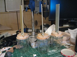 he bulkheads to the cover, and bolted them together. Once cured, I dry-fit the 3 G10 2.5” x 7” sleds into the dado slots of the bulkheads making sure there was no overhang. I then glued everything up, and left it overnight. While the glue was drying, I installe
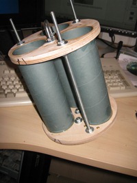 d the three all-thread rods through the two centering rings. This was actually a critical component, as the all thread would be secured through the center rings I had previously installed in the upper airframe. The main parachute kevlar shock cord would be connected to the U-bolt on the top of the av-bay, so the all thread, and center rings would be the only things connecting the main parachute to the rocket. Another great part of this hobby are the ‘cool’ tools you can buy, which could never normally be justified. In this case, my cool tool of choice was a digital toque wrench which enabled me to apply exactly the same amount of force on every bolt secured to the all-thread. In turn, th
 e extreme recovery forces should be evenly distributed through the rods. At least, this is what I told my wife when she saw the bill for the tools….
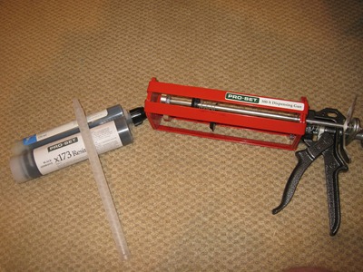 hesive epoxy I had used to tack on the fins, and build the motor tube. While I really like the E-120HP, once cured, it is almost impossible to sand. I’ve used it once before on external fillets, and when I went to sand them down, I wound up taking a lot of the fiberglass around the fillet, but not the fillet itself. Instead, I opted for
 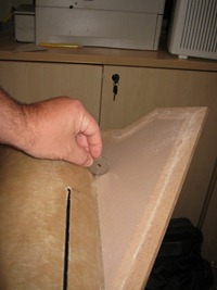 r, yet it can be wet sanded. I didn’t say it was easy to sand, certainly not like a traditional epoxy or laminating resin, but much better than hysol.
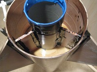
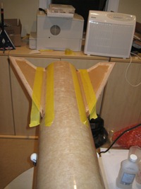 ake 1/2” airbrush masking tape and lay it down exactly on the marked guidline. The tape is now at the trailing edge of the fillet I am going to make, and willl ensure an even line once the epoxy has set. I should point out I’ve now coupled the upper and lower airframe together, to give me enough weight to secure the lower airframe to a PVC rocket holder. Since this have a very high set time, I need everything to be very secure for at least a day once complete.
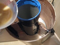
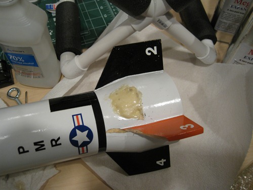
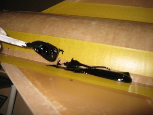 e has proven I don’t have the skills to make a good fillet with a gun and wand this big. I opt to fire the epoxy into a cup, and hand mix the epoxy the traditional way. Once mixed, I take a spoon, and fill the space between the masking tape. This stuff is really hard to control. It has a very high viscosity which makes it difficult to work with, but, of course, that’s what the tape is for. I then prepare a cup of isopropyl alcohol, lots o
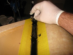 f paper towels, and a second cup to catch the excess epoxy.
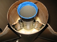
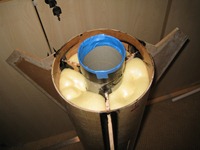
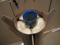
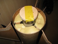
 I’m thinking about separating the nosecone at main deployment to ensure it doesn’t do any damage to the airframe. I recently got the Scott Glass Olgive nosecone in (Thank you Scott Broderick!), and it is rigid, and heavy!
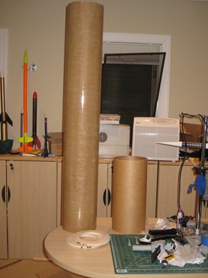
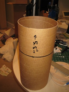 ctromagnetic deployment equipment. The extra length didn’t change any of the build plans for this portion. First up was to measure the coupler. 5.5” of the coupler is used to joining the two sections of the rocket, while the remaining space in the coupler will be housing the AV bay. I installed the coupler into the upper airframe up to the measurement point, then drew a complete line around the diameter of the coupler to indicate the section that would be left out, as well as drawing a line inside the airframe indicating where the coupler would end. I removed the coupler, then went about sanding both the outside of the coupler up to the line, and the inside of the airframe, down to the line. I shot a few lines of epoxy inside the airframe, a
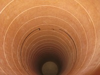 s well as on the outside of the coupler, then used a
 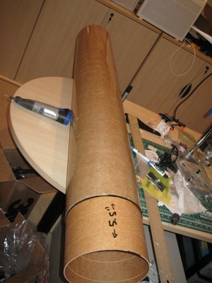 credit card to evenly coat both surfaces. So far, so good. Once again I clamped down the upper airframe and left everything to cure for the next 24 hours. I returned to a nicely epoxied coupler and re-measured everything to ensure nothing slipped overnight. The last step required was to install two centering rings into the airframe at the end of the coupler. The center rings each with 3 holes to allow the all thread of the AV bay to go through the center rings and get secured with wing nuts. This is a great design decision by Giant leap, as it *should* allow me to easily remove the AV bay for programming and prepping before a launch. When I went to install the couplers however, I cam to realize my arm won’t reach all the way through the upper airframe to both add glue, and position the two centering rings properly. The centering rings required fairly precise placement to ensure the all-thread holes were aligned properly. I couldn’t slide the center rings through the coupler end, as the
 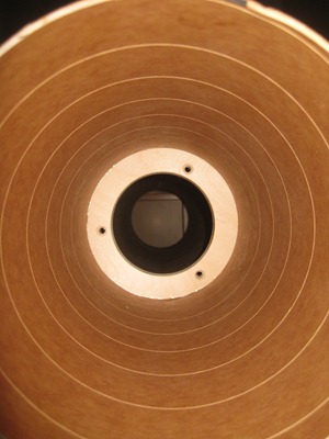 reduction in the inner diameter of the airframe was now sufficiently small to not let the center rings through. I then realized, even if I do figure this out (which I would), how in the world am I going to thread on the wing nuts onto the AV bay all thread when it comes time to install the AV bay? The solution to the second problem, turned out to be the solution to the first problem. I had NO interest in cutting a door on the rocket. Instead, I found a piece of spare PVC piping (I use it a lot to make rocket holders) cut it down to 18”, and used my dremel to cut out two ‘wingnut notches’ on either side of PVC wall. this will allow me to secure the wing nut into the PVC pipe, and use the PVC pipe as an elongated screw driver to install each of the wing nuts. I could also use the PVC pipe to push the center rings into place. the only real modification I had to do was CA the washers onto the forward facing center ring all thread holes – my little PVC trick won’t hold a washer correctly. Viola, mission accomplished. The only thing I don’t like about this solution is it now requires me to bring a custom build ‘tool’ to every launch I plan on flying this rocket. Time to add “Pack PVC wing nut driver” to my ever increasing pre-flight / pre-leaving home checklist. I waited another 24 hours, then did a trial run of installing the AV bay into the center rings. Bingo, they went right in, and my PVC pipe worked well as an elongated driver. Now that the upper airframe is complete, I can install it onto the lower airframe to add leverage to put the rocket on a stand, and start my external (and internal) fillets.
 from “
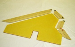 proper CG / CP. One of the issues you can clearly see wit this material is, it’s impossible to make a beveled leading edge with it. In my case I had custom MDF machined & mitered to cover all of the exposed edges. Just needed to bevel the MDF into a ‘tongue’, and use an exacto knife to build a ‘groove’ in the exposed edges. One REALLY nice things about the fly-lite material, is it is really easy to cut. In fact, I just drew around my template with a felt tip pen, and used a pair of shearing scissors to cut the line. You can’t
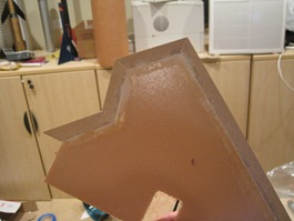 really get any easier than that! Of course, that means the perpendicular shear strength of the material is quite low. How low? well, the formula to compute shear strength is;
  While I don’t have the equipment to measure principal stress, I did use a piece to determine it’s ‘relative’ stre
 ngth. With the MDF epoxied in, there was no amount of stress parallel to the fiberglass sheeting I could create (using a complete set of weights) that would cause the material to fail. With perpendicular force however, it failed at about half the force of a duplicate sized piece of G10. My conclusion? Kevlar and fiberglass lamination.
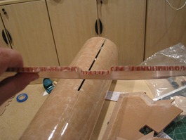
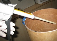 any fit issues. The only real complication was the upper fin tab would now be epoxied to the motor tube within an entirely closed portion of the airframe. I had already glued in place both center rings which would make it challenging to create inner fillets on the fin tab. My solution…. epoxy gun! for someone as messy as I, I tend to get epoxy in lot's of places it should never be. I found glue guns (both large, and small) to be REALLY helpful when you need to get a bead of epoxy in a very
 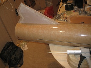 specific spot. They also have ‘mixing’ chambers within the tip, which mixes the two parts of epoxy as it exits the gun. This is VERY handy, although I have found it generally doesn’t mix epoxy nearly as well as doing it by hand in a measuring cup. In this case, I put a bead of epoxy on the fin tabs, then fit them into the through-the-wall fin slot. I left the fin on for a minute or so, then pulled it back out. Looking inside the upper fin tab slot, I could clearly see the line of excess epoxy left by the fin tab. I just inserted the epoxy tip through the slot, and put down a really nice bead of the high viscosity 120HP epoxy. I then reapplied another bead of expoy on the tab root, and the exposed lower centering ring, and reinserted the fin into the slot. I then put a little pressure tape across the outside edge of the fin to keep it in place, and clamped the airframe to my desk. peeking through the wing slots, I could cleary see a great motor tube / fin tab fillet had formed. The aft fin tab was open to viewing – it looked exactly like the upper tab without the big fillet, as I planned on making those later in the project, in conjuction with the outer fin fillets. turned out the lights, to let the epoxy cure for the next 24 hours.
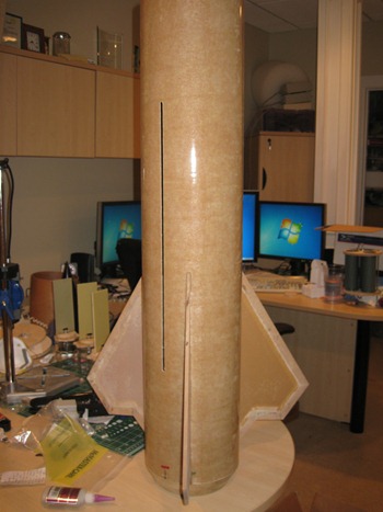
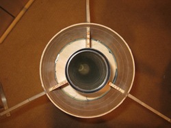 n adding video equipment in the rocket. There is nothing worse than watching a spinning rocket video – gives me a headache, and you really can’t see anything. Here’s a good