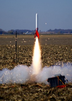
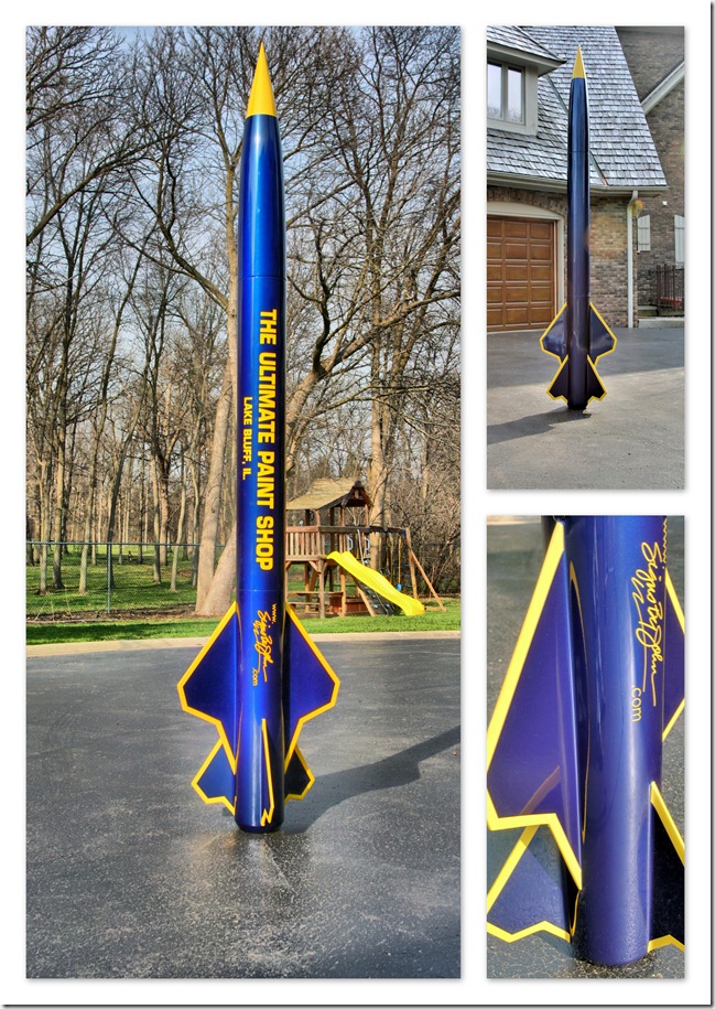
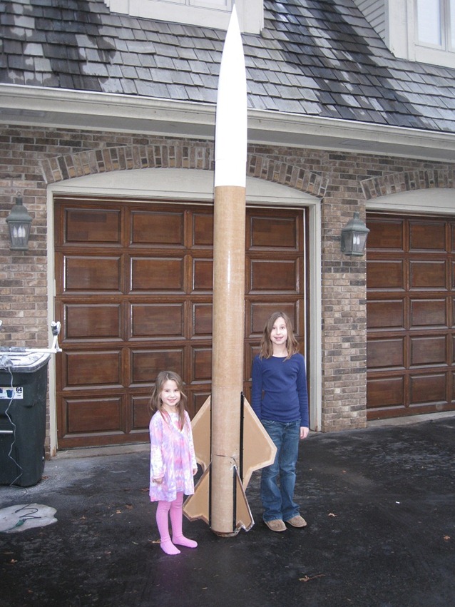
Sounds strange, but I like laminating things. Kevlar, Carbon Fiber, Fiberglass…. doesn’t really matter. Once you understand the process, it opens up a lot of options in both Rocketry, and the real world. In Rocketry, Laminating can provide key missing strength, stiffness, or just plain ruggedness to an otherwise undistinguished model. Combine lamination with foam, and a whole world of custom parts, or odd rockets can be created. In the photo on the right, you see what looks to be the launch of a boring Estes “Super Big Bertha” kit. In fact, the entire rocket was laminated with Kevlar, Carbon Fiber, and fiberglass. The end result – A kit that Este’s recommends launching with a D12-5 engine (max thrust of 29 N, total impulse of 16.8 N-s), that I launched with an Aerotech J570 (max thrust of 1142.5N, total impulse of 973.1N) – an engine about forty times more powerful. During this particular flight, I had packed the chute a bit too tight to fit in my electromagnetic ejection system. Ejection worked, but the parachute never inflated. The rocket fell from 5000 ft, and didn’t have a scratch on it when I found it about 1/2mile away. You can check out the video from the flight below (you can see the camera duct-taped to the side)
[youtube=http://www.youtube.com/watch?v=ptcmwxKvZdM&w=448&h=277&hd=1]
Super Big Birtha Freefall
Wh

ile I didn’t show the original fiberglassing of the magnaframe airframe, there wasn’t a lot of complexity involved. Just as I was leaving HPR rocketry the first time (thanks to the BATF), I had found a company called Fibersock that sold a knitted fiberglass “sock” that let you fiberglass a tube without any seams or complexity. Upon my return to HPR (thanks to Tripoli & NAR beating the ATF in court), Fibersock is gone, but the product is still around. Giant Leap sells a version they call “easyglas” which is exactly the same thing. Basically you pull the sock over the airframe, tie it up on either side, and slather on epoxy laminate. The only modification I’ve made to this process is to use a Teflon coated release film to ensure a very smooth surface, and no air bubbles. This is unlike any peel-ply, or release film I’ve ever used. Very easy to remove, very smooth, super easy to cut and position. Frankly, it’s so well made, when doing tip-to-tip lamination on a small rocket, I’ll often use the same piece of cut release film over and over. Only place I’ve found it i s
here.
My plan was to to do tip-to-tip lamination of the fins with one layer of Kevlar for strength, and one layer of
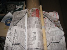
fiberglass for finishing. I’ve found Kevlar almost impossible to sand to a smooth finish once it is cured. a thin layer of fiberglass over the top of the Kevlar provides a great base to sand and smooth. I first laid some scrap newspaper over the fins to create the base outline of the fin area. I then cut out the newspaper, and used it as a base to build a cutting template out of foam board. The newspaper gave me the base dimensions, but I needed to add about 2 inches of cloth in each direction to ensure complete coverage, and allow for the Kevlar and fiberglass to wrap around the thick fin edge.
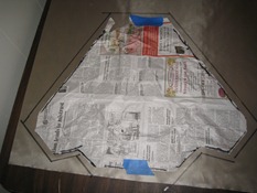
A typical rocket fin made out of g10 fiberglass would be about .093, to .125 inches thick. My fins and wings were about five times thicker, requiring some creative solutions down the road. My main goal in creating the laminating fin can is to ensure the fin’s don’t rip off during flight, and increase their strength in case the rocket lands funny. I plan on putting a LOT of time into the finish (I have an airbrush, and like to play….), and would be crushed if a great flight ended with a broken fin.
My normal method for tip-to-tip lamination is to use a fairly standard vacuum bag sealing process. Because of the size of the rocket, I could not create a bag that would encapsulate the entire lower sustainer with fins and keep a good seal. This may be possible, but I spent a LONG, LONG time on it. The primary advantage of vacuum sealing is it creates a lot of pressure on the lamination, squeezing the excess epoxy out through the r
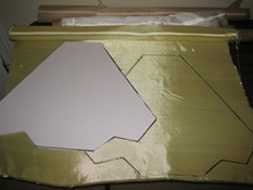
elease film (reducing weight), and creating a good mechanical connection between the epoxy, fabric, and fins. In my case, I was less concerned about weight, but wanted to make sure I would have a good mechanical bond, including the thick edge of the fins. There are lots of great tutorials on the web on how to do tip-to-tip lamination without vacuum sealing, but all of the ones I have seen assume you have a fairly thin fin. The best I’ve seen is
here. In my case, needed ballast on the lamination to keep it tightly bonded to the fin, but I needed pressure on the edge of the fin as well. Using a fin jig as John did in the link will almost guarantee there won’t be enough pressure on the edge of the fin. I needed some kind of Ballast that would mold around the fin keeping pressure over the entire surface area during curing. I settled on using a liquid as the weight, in a waterproof bag that could hang over the fin.
I should probably mention I spent a LOT of time sanding down the fillets. I also installed the boat tail, as I decided I wanted some lamination over the edge to ensure a smooth transition between the airframe and boat tail for
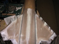
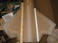
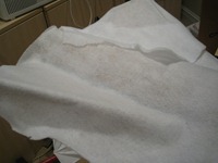
finishing. That added even more sanding. Once complete, I ‘painted’ on a layer of epoxy (US Composites), put down the Kevlar, Wet the Kevlar, then added the fiberglass. Wet the fiberglass, then added the Teflon release film. Wet the release film, then added a Polyester breather cloth on top to suck up the excess epoxy, and provide a surface for me to put down my ballast. I filled three zip-lock bags about 3/4 with water as my ballast. One bag
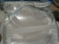
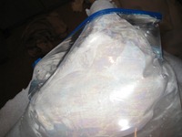
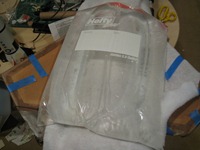
per fin, and one for the airframe & fillets. I know it’s kind of hard to see, but the bags on the fins hang over the side, providing positive pressure on the lamination during the cure. I left everything for 24 hours. Removed the water bags, then the Teflon release film.
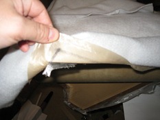
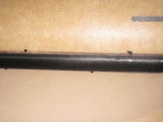
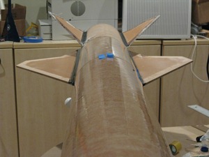
As you can see, it came out really, really well. I was a little worried with the lack of significant weight on the wings, I would get a lot of air bubbles in the lamination over the fillets. big curves like this are notoriously difficult to make sure the Kevlar and fiberglass stay pressed against the fillet, especially when the water bags were pulling on the edges of the weave to secure them around the fins. . There wasn’t one bubble tip-to-tip. Happy with the process, I then repeated it twice more for each side.
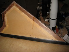
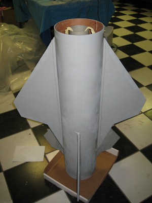
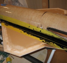
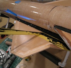
I only had two issues with the process, neither was too critical. First, on the edges of each Fin, I had doubled the lamination. The second layer of lamination didn’t have the pressure of the first, which you can see looks like an air bubble along the leading edge of the fin. This isn’t a big deal, As I will be sanding down the second layer, which is mostly fiberglass. The second issue you can also see in the picture on the left is a few epoxy runs. This is a run of epoxy over a side of lamination that has already dried. Again, not too big of a deal, just requires sanding. As you can see from the picture above, I had to laminate over the pre-cut slots for the wings to get a true tip-to-tip fin can. The pre-cuts were already too small, so the next phase will be to sand the fin can, re-cut the wing slots, and install the wings. Should start to look like a real rocket soon.
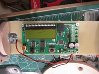
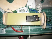
 when you look at it in this big AV bay. The raven is more complex to install since it uses a common + wiring scheme. While the Marsa4 had discrete connectors for everything (a + and - for each e-match, the battery, and the power switch), the Raven only has 4 terminals and a battery + for everything. This means the power switch has to be inline, and each e-match has to be connected to the same + battery post. Not a big deal, and great if you are putting this in a minimum diameter rocket. With the amount of space in my AV bays, it’s kind of unnecessary. That said, this is my most
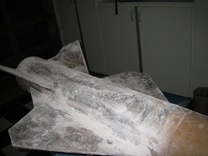 I ended up with on the wing tops and fin can. Worse, I can’t really fit an electrical sander in that area, so I’ve had to create all sorts of sanding devices to get into that area. You can see what looks like multiple colors on the wings and fins in the picture on the left. This is indicates in some areas I have sanded through the top layer of fiberglass into the Kevlar. That’s not necessarily a good thing,
 put a damper on rocket building and pretty much everything else. Worse, I have taken a lot of my OLD rockets out of storage few weeks ago (a Brutus, Maximum Thrust Thunderbird, and a few other 15+ year old HPR rockets) to show my kids, and clean up for flying this weekend at Bong. Given how thick the snow is, I can’t imaging wading through it all in my leg cast trying to recover the rockets
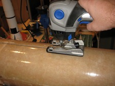
 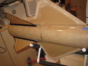 to get the wings on. First, I had to re-cut the wing slots. The lower portion was glassed over when I made the fin-can, and the whole slot itself wasn’t quite thick enough for the wings to fit through. I repeated the process on the other side, until I could dry fit both wings with a tight fit. One of the issues I will have with the wings is my limited ability to make interior fillets since both sides of the centering rings are already glued in place. First, I filled the interior of the wing’s nomex honeycomb with epoxy and put it into the slot. I let the epoxy ooze out of the honeycomb, then removed the fin. This gave me a line of epoxy on the motor tube where the wing made contact. I repeated that process a few times to build up the epoxy on the motor tube. I then drilled a few half-holes in the wing-slots which allowed me insert a syringe into the body and add epoxy for a sloppy, but effective internal fillet on each side of the wing. Once it was dry, I was able to look through the upper center ring hole I made to pour foam to ensure a the wing was touching, and had a a fillet, and taped it up to cure. I repeated the same process on the other side until both wings were secure w
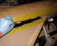 ith internal fillets.
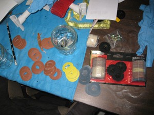
 was a little more tricky than the fins because the wing is more than twice the length. Worse, there was not enough clearance between the wing
  and the fin for me to use the same diameter washer I had used on the fins. Eventually, I settled on using my finger to spread, and create the fillet, dipping it in alcohol between pulls, exactly like using the washer. The result was significantly more messy,
 but just as effective in creating a very smooth fillet, with clean lines. This will reduce the amount of sanding I will have to do before glassing the fins.
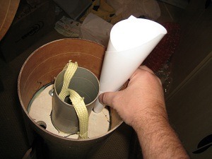 sustainer which I was using as a lever to keep the lower sustainer in my rocket holder to mount the sustainer upright. It’s foam time! Once again I calculated the empty volume on each wing side, mixed the proper amount (266 ML, half part A, half part B), made a quick funnel out of paper and poured in the foam. Within about 5 minutes, the foam had expanded, almost perfectly to the bottom of the pour hole. I love it when a plan actually works so well! I repeated the same process on the other side, mixing exactly the same amount of foam, but when it was done expanding, I could barely see to top through the pour hole.
 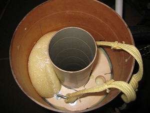 Yikes! Luckily, my kids weren’t around to see the utter failure of math and science’s ability to predict an outcome. II now had no idea how much volume was left in the sustainer, so I had to do the one thing I hate to do…. guess. As you can imagine, I didn’t guess right, and you can see the results on the right – an oozing mess out of the top of the second pour
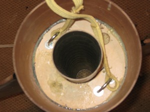 hole. Luckily, this is not as bad as it looks, and I have a fair amount of experience digging foam out of tight spots thanks to a lot of lawn darts during my magnetic ejection trials. five minutes with my trusty foam extractor (a special grapefruit knife), and a little sanding, and it almost looks like I got it right the first time. I’m now going to move everything out of my office and into my garage in preparation for the massive amount of sanding I’m going to need to do. I would like to thank an anonymous reader for the tip on where to find sanding discs for my 3d sander. A kit of 100 can be had at a retailer named Micro-Mark
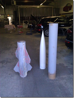
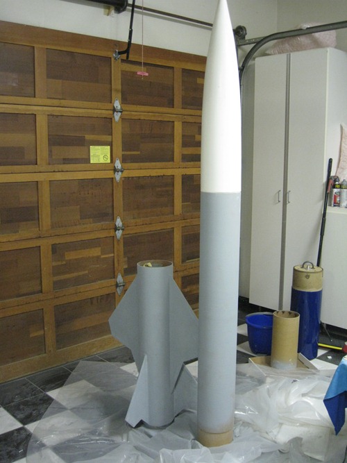
 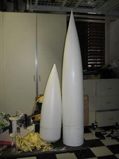 Spent much of the day cleaning up from the snowstorm. My four kids were school free yesterday, so I spent the day shoveling, and playing in the snow with them. I did find a little time for the rocket. The picture on the left is the original plastic nosecone. The one on the right is it’s
 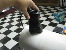 this in my office. You would be surprised at the amount of fiberglass dust even a small sanding can create. For sanding curved surfaces, I use a Crasftman 3D sander. The sander has three floating heads each with their own circular sanding pad. This lets the sander conform to most curved surfaces, reducing the possibility of creating a slat spot using a traditional sander. Unfortunately, they don’t seem to make these anymore, so the pads are becoming a little hard to find. This is an indispensable tool for me, so if someone knows of a reasonable alternative, let me know!

 ile I didn’t show the original fiberglassing of the magnaframe airframe, there wasn’t a lot of complexity involved. Just as I was leaving HPR rocketry the first time (thanks to the BATF), I had found a company called Fibersock that sold a knitted fiberglass “sock” that let you fiberglass a tube without any seams or complexity. Upon my return to HPR (thanks to Tripoli & NAR beating the ATF in court), Fibersock is gone, but the product is still around. Giant Leap sells a version they call “easyglas” which is exactly the same thing. Basically you pull the sock over the airframe, tie it up on either side, and slather on epoxy laminate. The only modification I’ve made to this process is to use a Teflon coated release film to ensure a very smooth surface, and no air bubbles. This is unlike any peel-ply, or release film I’ve ever used. Very easy to remove, very smooth, super easy to cut and position. Frankly, it’s so well made, when doing tip-to-tip lamination on a small rocket, I’ll often use the same piece of cut release film over and over. Only place I’ve found it i s
  fiberglass for finishing. I’ve found Kevlar almost impossible to sand to a smooth finish once it is cured. a thin layer of fiberglass over the top of the Kevlar provides a great base to sand and smooth. I first laid some scrap newspaper over the fins to create the base outline of the fin area. I then cut out the newspaper, and used it as a base to build a cutting template out of foam board. The newspaper gave me the base dimensions, but I needed to add about 2 inches of cloth in each direction to ensure complete coverage, and allow for the Kevlar and fiberglass to wrap around the thick fin edge.
 A typical rocket fin made out of g10 fiberglass would be about .093, to .125 inches thick. My fins and wings were about five times thicker, requiring some creative solutions down the road. My main goal in creating the laminating fin can is to ensure the fin’s don’t rip off during flight, and increase their strength in case the rocket lands funny. I plan on putting a LOT of time into the finish (I have an airbrush, and like to play….), and would be crushed if a great flight ended with a broken fin.
 elease film (reducing weight), and creating a good mechanical connection between the epoxy, fabric, and fins. In my case, I was less concerned about weight, but wanted to make sure I would have a good mechanical bond, including the thick edge of the fins. There are lots of great tutorials on the web on how to do tip-to-tip lamination without vacuum sealing, but all of the ones I have seen assume you have a fairly thin fin. The best I’ve seen is


 I only had two issues with the process, neither was too critical. First, on the edges of each Fin, I had doubled the lamination. The second layer of lamination didn’t have the pressure of the first, which you can see looks like an air bubble along the leading edge of the fin. This isn’t a big deal, As I will be sanding down the second layer, which is mostly fiberglass. The second issue you can also see in the picture on the left is a few epoxy runs. This is a run of epoxy over a side of lamination that has already dried. Again, not too big of a deal, just requires sanding. As you can see from the picture above, I had to laminate over the pre-cut slots for the wings to get a true tip-to-tip fin can. The pre-cuts were already too small, so the next phase will be to sand the fin can, re-cut the wing slots, and install the wings. Should start to look like a real rocket soon.
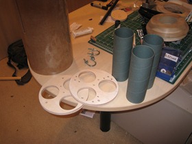
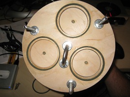
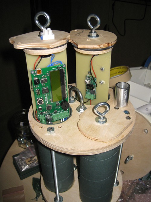
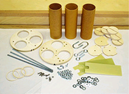 Three 2.5” x 8 phenolic tubes
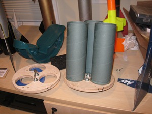 othing is ever as it seems
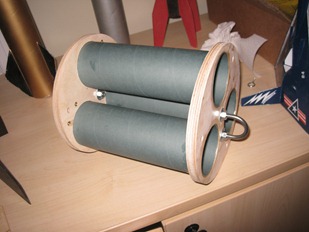
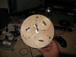
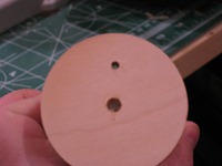
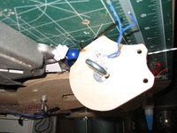
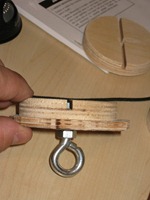 ade sure they were true, and moved to putting together the top of each pod. Oops! when putting the eyebolt through the cover, and top bulkhead with the dado slot, it became obvious the eyebolts were too small. Before going out and buying new ones, I measured EVERYTHING to ensure the bulkheads or cover’s were not cut wrong. I also email Giant Leap just to be sure. A quick stop at home depot, and I was back in business. I then threaded the eyebolts, glued t
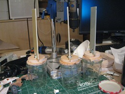 he bulkheads to the cover, and bolted them together. Once cured, I dry-fit the 3 G10 2.5” x 7” sleds into the dado slots of the bulkheads making sure there was no overhang. I then glued everything up, and left it overnight. While the glue was drying, I installe
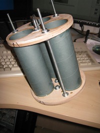 d the three all-thread rods through the two centering rings. This was actually a critical component, as the all thread would be secured through the center rings I had previously installed in the upper airframe. The main parachute kevlar shock cord would be connected to the U-bolt on the top of the av-bay, so the all thread, and center rings would be the only things connecting the main parachute to the rocket. Another great part of this hobby are the ‘cool’ tools you can buy, which could never normally be justified. In this case, my cool tool of choice was a digital toque wrench which enabled me to apply exactly the same amount of force on every bolt secured to the all-thread. In turn, th
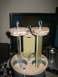 e extreme recovery forces should be evenly distributed through the rods. At least, this is what I told my wife when she saw the bill for the tools….